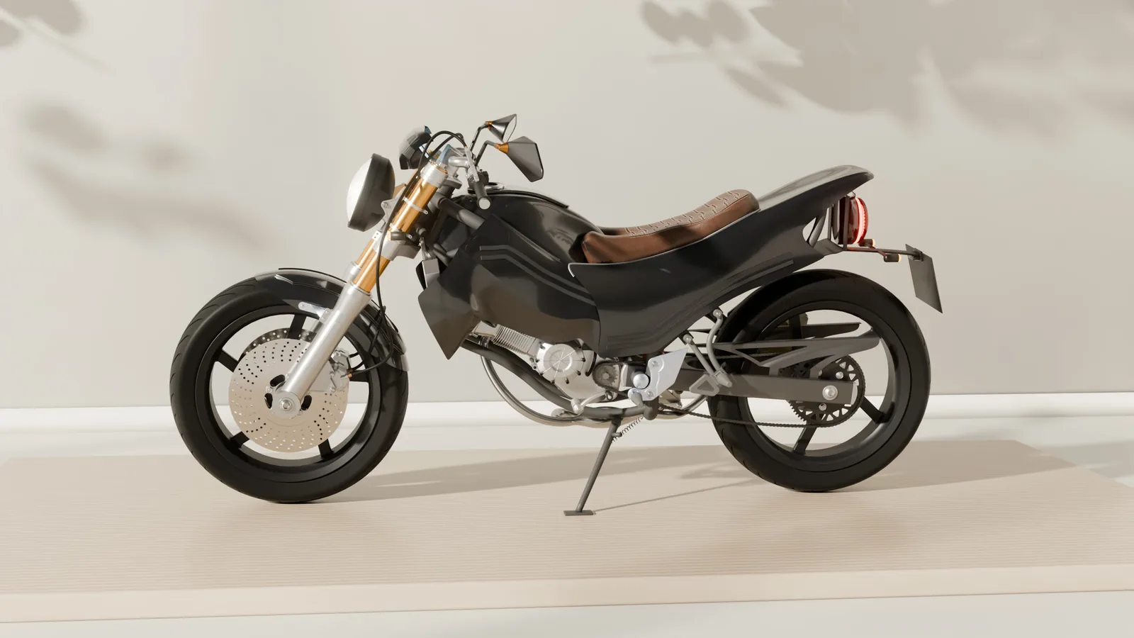
Café Racer Concept
I rebuilt a complete motorcycle in SolidWorks from a training model, then treated it as if it had to be built and ridden: found its loads, analysed the frame and gearbox, fixed what failed, and planned how two key parts would be made.
- CAD
- 217 parts, 41 assemblies, 42 drawings
- Frame
- FoS 0.27 → 1.14
- Output shaft
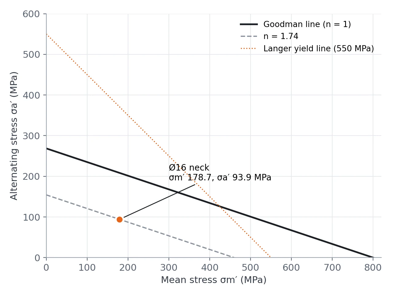
- Fatigue FoS 1.74, infinite life
- Tools
- SolidWorks · ANSYS · Blender
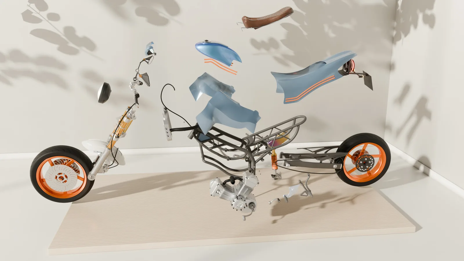
The whole bike, part by part.
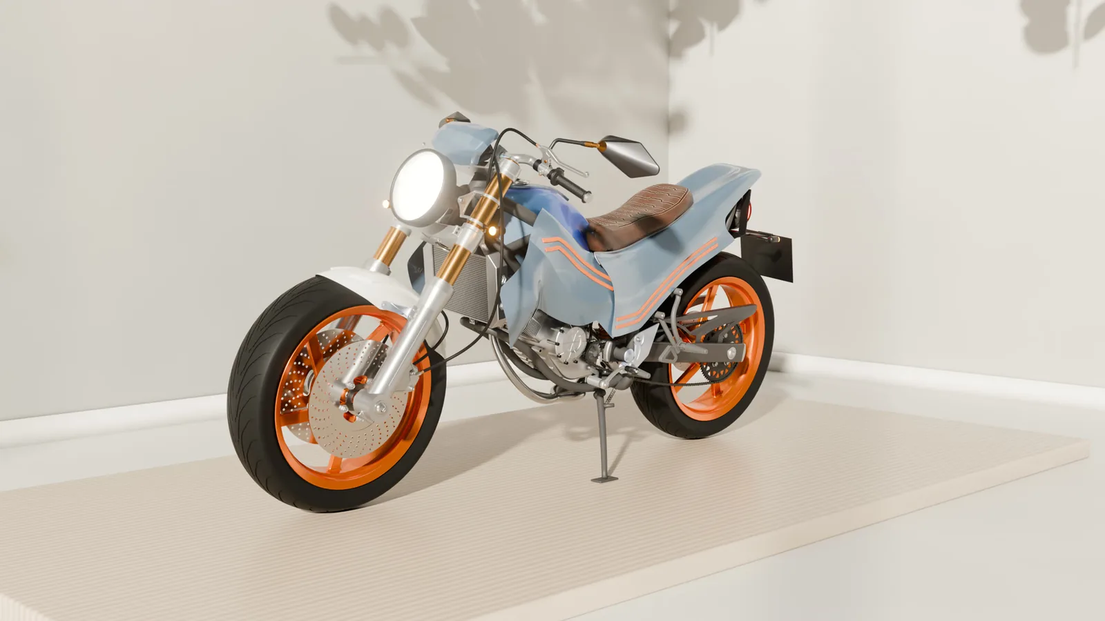
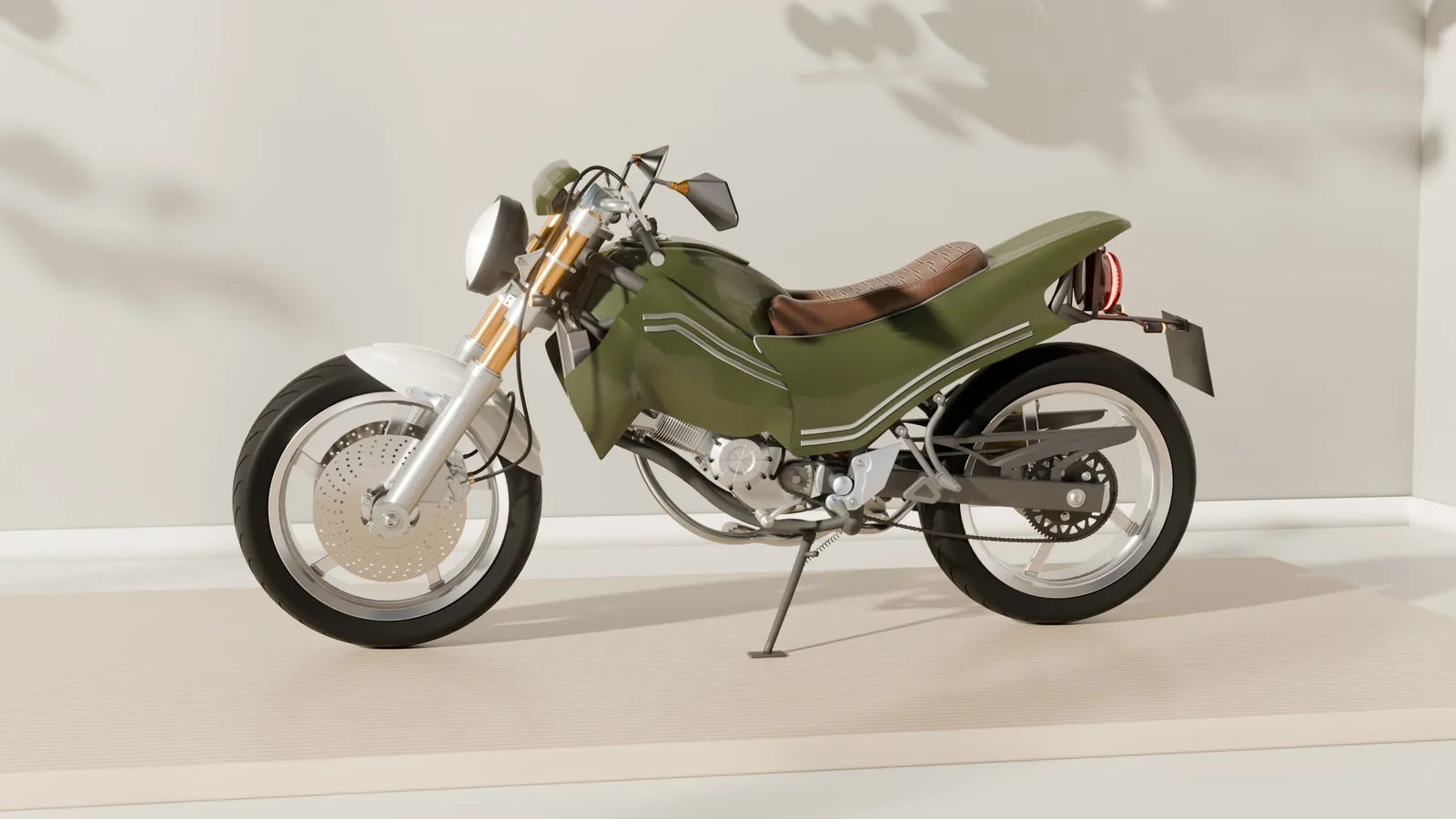
Every part was modelled in SolidWorks and built up through sub-assemblies into one top-level assembly. The bodywork (tank, seat, side and rear panels) is my own design.
The CAD engine weighed only 18.4 kg: thin walls, a hollow flywheel, no starter. I set it to 36 kg for the load cases, because a light engine would have hidden the real frame loads.
| Engine | Parallel twin, Ø60 bore, 250 cc class |
| Gearbox | 5-speed · primary 1.571 · 1st 2.00 |
| Wheelbase / head angle | 1403.54 mm / 33.0° |
| Seat height | 740 mm |
| Mass | 151.75 kg dry (CAD) · 162 kg wet |
| Front / rear split | 40.4 / 59.6% with two riders |
The frame failed. Thicker tube didn't fix it.
Load case
A hard bump briefly triples every weight on the bike. I stacked that on a rider and a passenger (312 kg in total) so the frame is sized for the worst day, not an average one. Loads go in where parts bolt on: the engine into its four mounts, the riders onto the seat rails, and the suspension forces onto the shock tab and linkage bracket, each solved by hand through the rising-rate linkage.
The rear wheel carries 5469.9 N at 3 g, but the shock pushes on the frame with 23 215 N: 7.6 times the weight of the whole loaded bike.
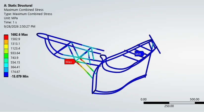
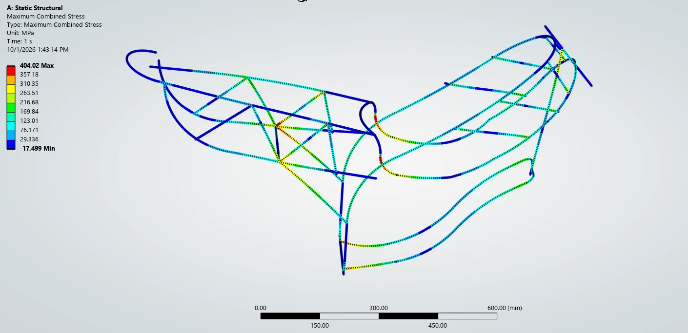
The problem was how the load entered the frame, not how thick that one tube was.
Why it failed
The shock pushes the frame up with 23 kN while the swingarm pivot, only 244 mm below, pulls it down. In the original frame that path ran through Ø12 solid bars loaded in bending. Even standing still with two riders it sat at 564 MPa, above yield.
What I changed
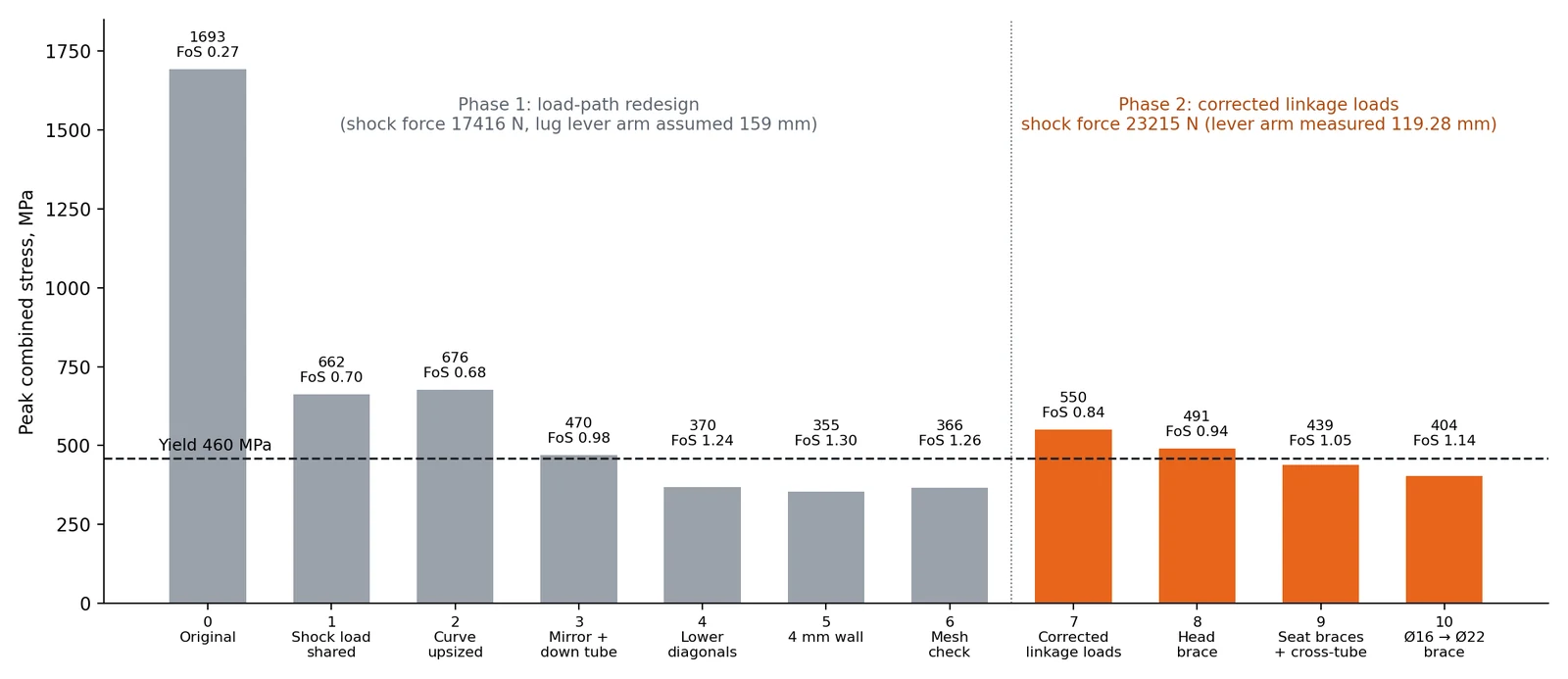
AISI 4130 normalised tube, yield 460 MPa. I changed only the tubes on that load path: shock-area curves, down tube and lower diagonals to Ø35×30, and the two highest-loaded members to a 4 mm wall. My first instinct, upsizing the tube with the peak, did nothing (661.5 → 675.9 MPa).
Result
FoS 0.27 → 1.14 in the worst case. Tail deflection 59.8 → 8.6 mm. Frame mass 18.1 → 20.5 kg (+13%) for 4.2× lower peak stress. This is a static check only; weld fatigue and heat-affected-zone strength are next.
How I knew the model was right
A free-free modal run gave exactly six rigid-body modes, so every tube was connected. The steering-head reaction landed 2.0% from my hand calculation. Halving the mesh size changed the peak by only 3.2%.
A sideways hit governs, not the chain.
| Load case | Peak stress | FoS | Deflection |
|---|---|---|---|
| 3 g vertical bump | 295.6 MPa | 1.56 | 3.59 mm |
| Chain pull 2218 N, one side | 36.1 MPa | 12.7 | 0.35 mm |
| Steady cornering, 45° lean (scaled from the bump run) | ≈ 139 MPa | ≈ 3.3 | ≈ 1.7 mm |
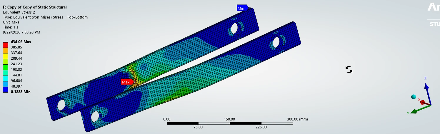
| Lateral envelope: 1 g vertical + 1 g sideways | 434.1 MPa | 1.06 | 6.45 mm |
Reading it
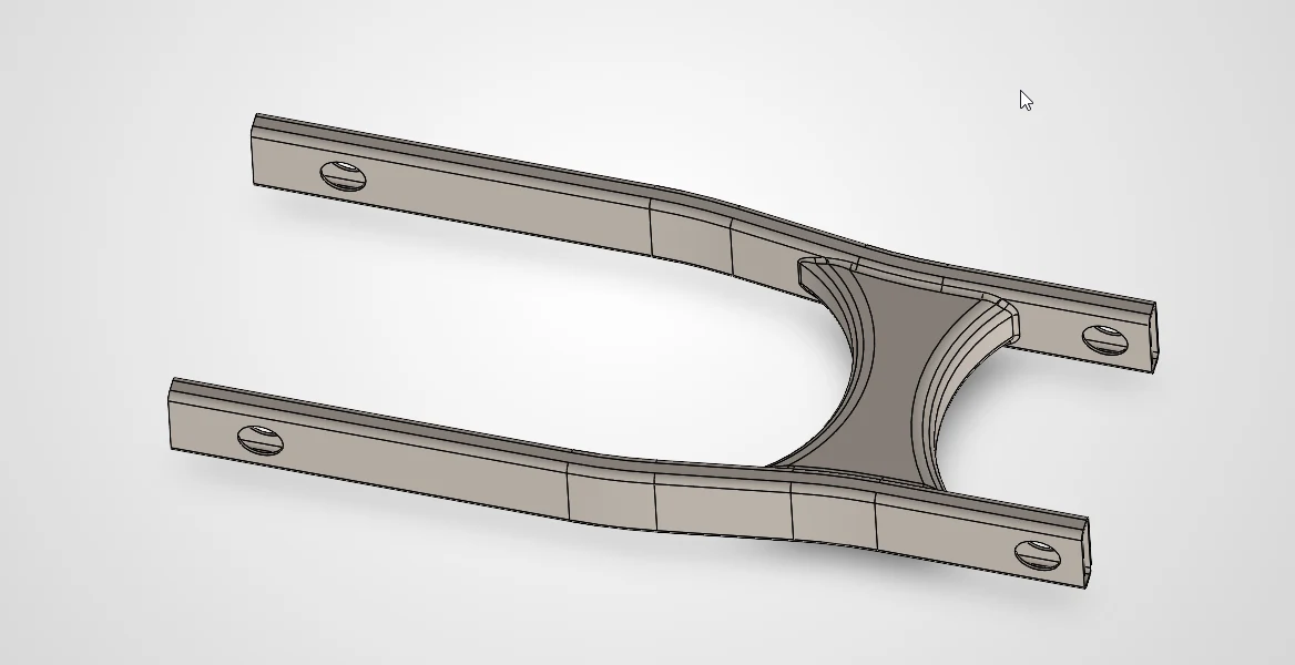
The arm is 60 mm tall but only 18 mm wide, so it is 7.3× stiffer and 2.2× stronger up-and-down than sideways. A genuine sideways load (a crossed-up landing, a kerb strike, a sliding tyre suddenly gripping) finds that weak axis.
My hand calculation had flagged the chain pull as the worst case at 311 MPa, treating it as sideways bending. The FEA showed the chain pulls along the arm, so the arm carries it mostly in tension: 36 MPa.
Lightweighting, in progress
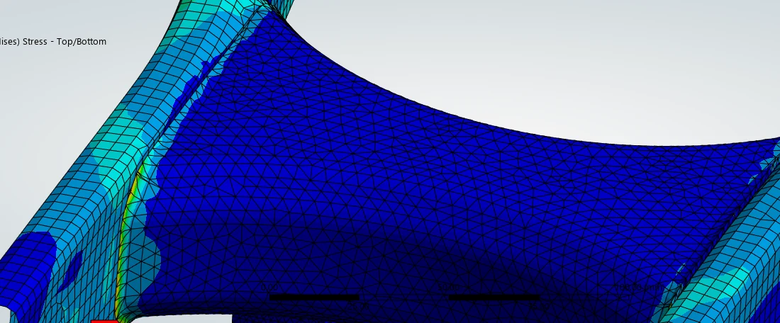
The 4.90 kg solid crossmember sits mostly below 70 MPa while the arm walls next to it carry 300. A topology run at 35% retained mass empties the core and keeps material on diagonal paths from the lug bosses to each arm joint. Swingarms are welded from tube and plate, so I'm using that result as a map of load paths, not a part: a round cross-tube with gussets is being modelled now.
The shaft passes fatigue. The gear teeth don't.
Following the torque
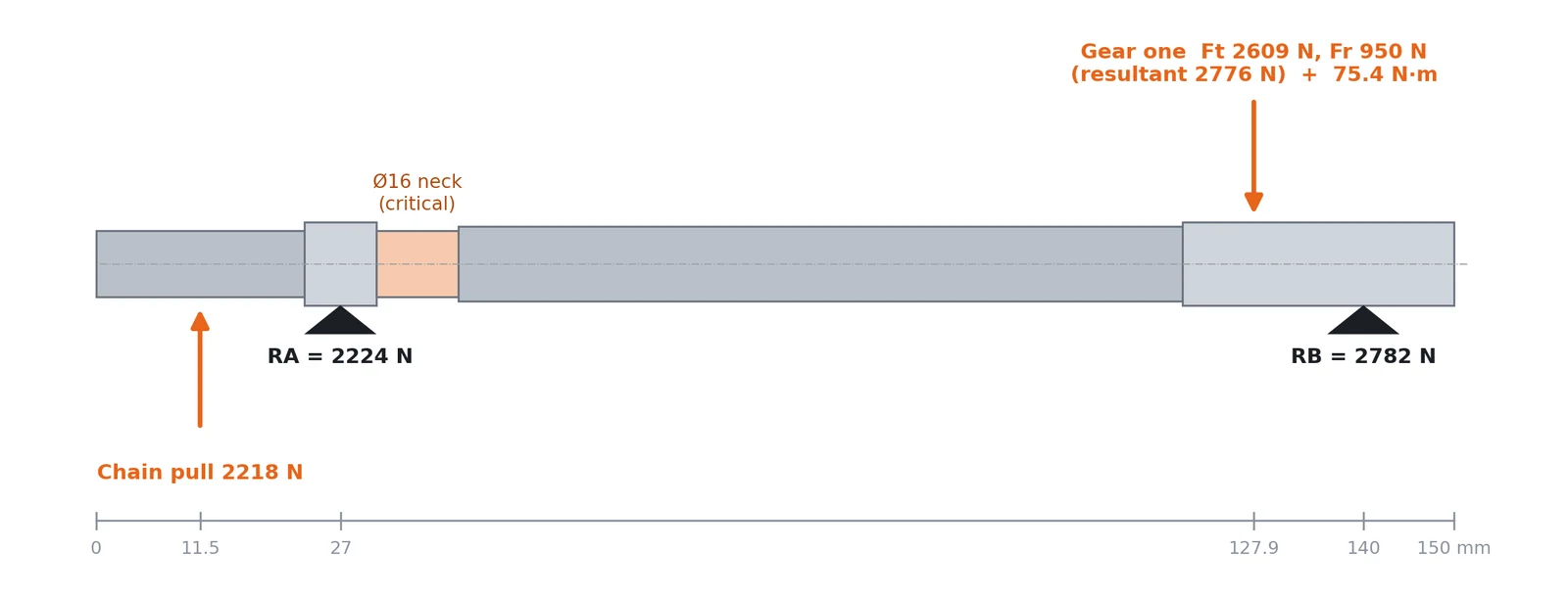
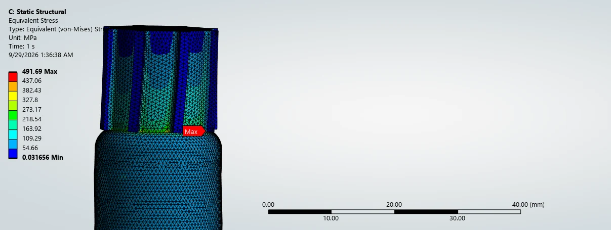
24 N·m at the crank × 66/42 in the primary drive × 52/26 in 1st gear = 75.4 N·m on the output shaft: 3.1 times the engine's torque, on a neck only 16 mm across. That neck is the thinnest section, carries the full torque, and sits beside bearing A where the sprocket's overhang moment peaks. By hand: 183.5 MPa von Mises, FoS 3.0. The FEA later agreed on the location.
Conclusion
The shaft is fine; the teeth are the weak link. The current 1st-gear pair (module 1.1, 8 mm face) reaches 1511 MPa in bending against a 379 MPa limit. A resized pair (module 2.5, 16 mm face) passes bending at FoS 1.28 but is still marginal in pitting, so it needs about a 20 mm face. Resizing moves both shafts and the cases, so it is logged as future work.
Two parts taken to a making plan.
Output shaft: bar to ground journal
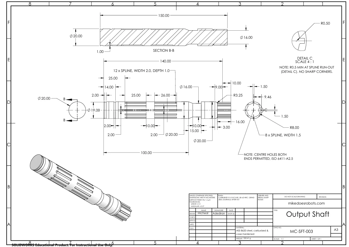
Every operation holds the shaft between the same two centre holes, so all diameters stay concentric. Carburizing distorts the shaft slightly, so the bearing seats are left 0.2 mm big and ground to size afterwards. The spline-end singularity from the FEA became a drawing note: R0.5 minimum run-out, which the gear-shaping cutter leaves for free.
- Op 10–20Cut 8620 bar Ø22 × 155; face, centre-drill
- Op 30CNC turn between centres, seats +0.2 mm
- Op 40Hob 12-spline; shape 8-spline
- Op 50Carburize 0.5–0.8 mm, 58–62 HRC
- Op 60–70Grind Ø20 k5, Ra 0.4; inspect
Right engine case: A356-T6 permanent-mould casting
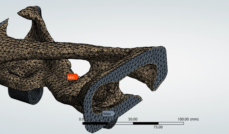
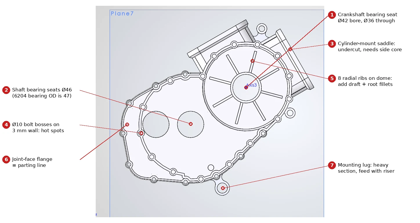
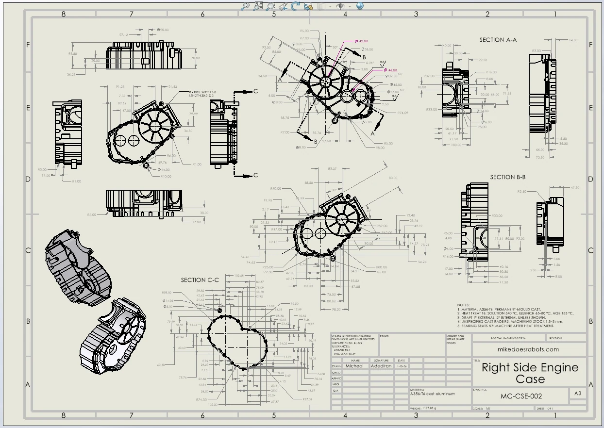
The model had been drawn like a machined part: no draft, 3 mm walls meeting Ø10 bosses, R1 inside corners and an undercut saddle that needs a side core. The review produced seven fixes, from 1°/2° draft and cored bosses to a side slide for the saddle.
It also caught a part that could not be bought. The gearbox bearing seats were drawn at Ø36, but no catalogue bearing for a Ø20 shaft is 36 mm outside. The nearest real part is a 6904 (20 × 37 × 9), so the seats became Ø37 N7. By 100 °C the aluminium seat opens by 0.029 mm, enough to wipe out almost all of the interference, so the seats get retainer plates.
From assembly tree to seventy seconds.
- CADEvery part modelled in SolidWorks 2026 and built up through sub-assemblies.
- ExportA VBA macro walks the assembly tree and exports each sub-assembly to glTF, so the Blender scene keeps the CAD structure.
- RenderingMaterials, lighting and animation in Blender 5.2 with Cycles. 1,620 frames at 2560 × 1440 on a render farm.
- EditCaptions and the end card are added by a Python script in Blender's sequencer.
- SoundA second script builds the music edit, engine and synthesized effects and masters the mix.
Credits
The project started from the part reference drawings in Christopher Rothera's Udemy course "PTC Creo Parametric - Full Motorbike Build", which I remodelled in SolidWorks. The bodywork is my own design, the frame was redesigned to pass structural analysis, and a number of other parts were modified along the way. Music: "Hard EDM" by kulakovka, from Pixabay. Studio lighting from Poly Haven; several materials from BlenderKit.